


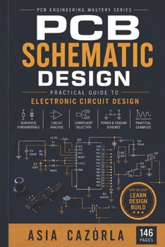
PCB Schematic Design: Practical Guide to Electronic Circuit Design

EXPANDED PRINT EDITION - A more detailed and comprehensive guide to professional electronic schematic design.
PCB Schematic Design - Practical Guide to Electronic Circuit Design is an expanded print reference for learning how to transform electronic concepts into clear, structured, reviewable, and PCB-ready schematics.
This paperback edition has been developed as a more extensive learning and reference resource, with expanded technical explanations, additional engineering content, practical examples, diagrams, and visual material designed for detailed study.
A professional schematic is far more than a drawing of connected components. It is the technical foundation of the entire hardware development process. It defines electrical connectivity, communicates design intent, supports engineering reviews, guides PCB layout, and provides essential information for debugging, manufacturing, and future product maintenance.
This book explains how professional electronic circuits are planned, organized, documented, reviewed, and prepared for physical PCB implementation.
Inside this expanded print edition, you will explore:
- Professional schematic design methodology
- Electronic symbols, net conventions, and reference designators
- Functional block diagrams and system-level planning
- Component selection and circuit documentation
- Power-supply architecture and power-tree development
- Voltage regulation and power-distribution concepts
- Microcontroller support circuits
- Reset, clock, boot, and programming interfaces
- Analog and digital circuit organization
- Grounding and power-net strategies at the schematic level
- Decoupling strategies and capacitor selection
- UART, SPI, I C, CAN, and other common interfaces
- Connectors, protection circuits, and external interfaces
- Hierarchical schematic design for complex projects
- Test points and design-for-debug considerations
- Electrical Rule Checking (ERC) and systematic design review
- Common schematic mistakes and how to avoid them
- Preparing schematics for PCB layout and manufacturing
- Documentation practices for professional hardware development
The expanded print format provides additional space for detailed explanations, technical illustrations, schematic examples, functional diagrams, engineering notes, and practical design considerations.
Rather than teaching readers simply how to place symbols and connect wires in an EDA tool, the book focuses on the engineering logic behind a well-designed schematic: how circuits are divided into functional blocks, how interfaces are documented, how power architecture is organized, and how design intent is communicated clearly to other engineers.
Who is this book for?
- Electronics and electrical engineering students
- PCB and hardware designers
- Embedded-systems developers
- Junior electronic engineers
- Makers moving toward professional hardware development
- KiCad and EDA users who want to improve schematic quality
- Engineers seeking a practical desktop reference for circuit documentation
Whether you are designing a microcontroller board, an embedded system, or a more complex electronic product, this expanded print edition provides a structured framework for creating schematics that are clear, scalable, reviewable, and ready for professional PCB development.
Design the circuit. Structure the system. Document the intent. Build a stronger foundation for the PCB.
PCB Schematic Design is part of the PCB Engineering Master Series, a professional reference collection covering the complete PCB development journey from fundamentals and schematic design to layout, manufacturing, debugging, signal integrity, RF, EMC, power electronics, reliability, and advanced industry applications.
Customer Reviews
ThriftBooks ® and the ThriftBooks ® logo are registered trademarks of Thrift Books Global, LLC